An electrochemical surface finishing process that creates a durable, corrosion-resistant oxide layer on aluminum and other metals — enhancing hardness, appearance, and long-term performance.
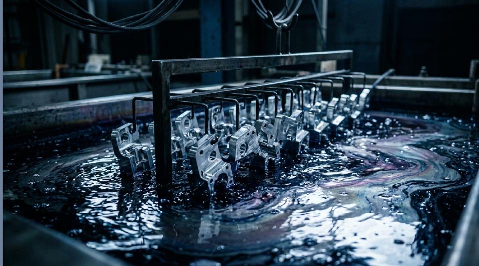
Anodizing converts the metal surface into a controlled oxide layer through an electrochemical process, producing a finish that is integral to the substrate — not applied on top.
Understanding both the strengths and constraints of anodizing ensures you make the right finishing decision for your application.


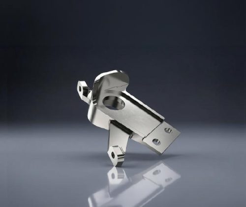
Anodizing delivers both functional protection and premium aesthetics, with results that vary by type and processing parameters.

Salt spray resistance exceeding 336 hours (Type III). The integral oxide barrier shields against moisture, chemicals, and environmental exposure without peeling.

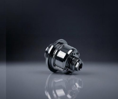
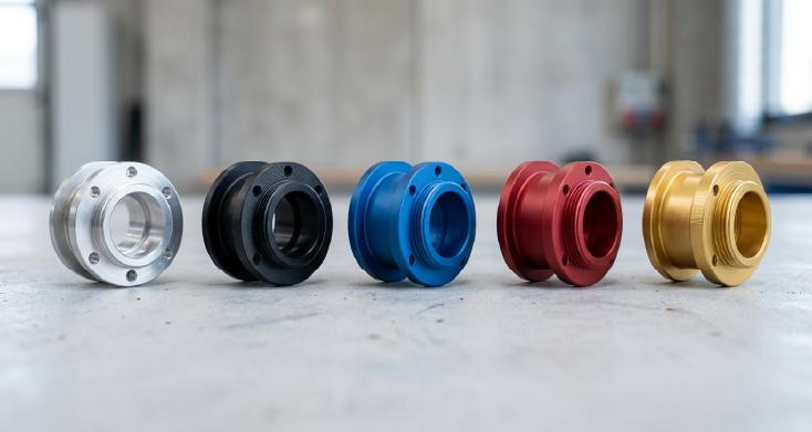
Wide palette from natural silver to black, blue, red, gold, and custom colors. Dyed finishes are UV-stable and maintain vibrancy for years in outdoor environments.

Hard anodizing (Type III) achieves 60–70 HRC equivalent hardness, providing excellent abrasion and scratch resistance for high-wear components.

The aluminum oxide layer provides dielectric breakdown voltage up to 600V for standard anodizing, making it ideal for electronic enclosures and insulating components.

Anodized surfaces withstand continuous temperatures up to 2,000°C (melting point of Al₂O₃) — far exceeding the base aluminum's limits.

Achieves matte, satin, or bright finishes depending on pre-treatment. Surface roughness as low as Ra 0.4µm for precision cosmetic applications.
| Type I Chromic Acid Anodizing | Type II Sulfuric Acid Anodizing | Type III Hard Anodizing | |
|---|---|---|---|
| Thickness | 0.5 – 7 µm | 5 – 25 µm | 25 – 80 µm |
| Hardness | Moderate | Good | 60–70 HRC |
| Corrosion Resistance | Good | Very Good | Excellent |
| Color Range | Limited (clear/gray) | Full spectrum | Dark gray to black |
| Best For | Aerospace, fatigue-critical parts | Consumer products, enclosures | Wear surfaces, military, industrial |
Anodizing is primarily designed for aluminum and its alloys, though a small number of other metals can also be anodized under specific conditions. The alloy composition directly impacts coating quality, color consistency, and corrosion performance.
For best results, choose alloys with low copper and silicon content. Wrought alloys generally produce more uniform and visually consistent finishes than cast alloys.
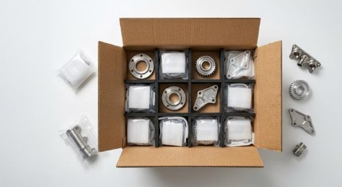
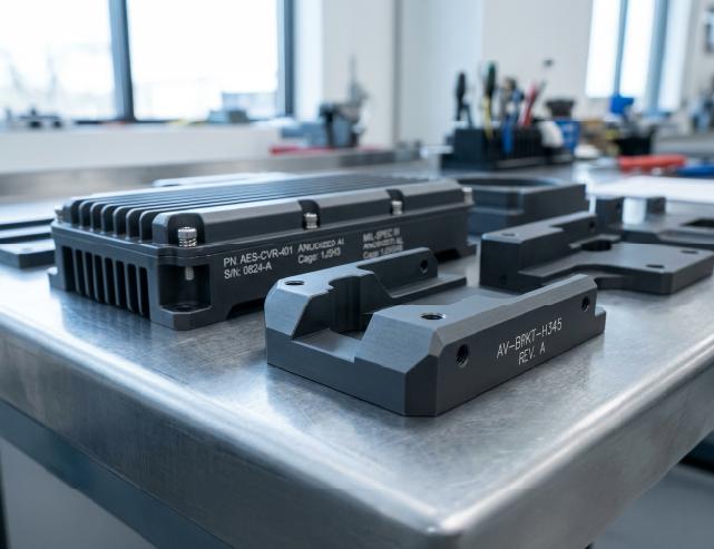
Anodizing serves industries demanding both functional performance and visual quality — from mission-critical aerospace hardware to everyday consumer electronics.
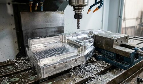
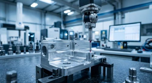
Designing for anodizing requires understanding how the oxide layer affects dimensions, surface quality, and functional features. Follow these guidelines for optimal results.
The anodic layer grows approximately 50% into and 50% out from the original surface. For a 25µm coating, expect ~12.5µm dimensional increase per side. Size critical features accordingly.
6000-series alloys (6061, 6063) produce the most uniform, cosmetically consistent results. Avoid high-silicon casting alloys for decorative applications.
Anodizing amplifies surface imperfections. Machine or polish to the desired finish quality before processing — Ra ≤ 0.8µm recommended for cosmetic parts.
Uneven material thickness causes uneven current distribution, resulting in inconsistent coating thickness and potential color variation across the part.
Identify areas requiring masking (threaded holes, mating surfaces, electrical contacts). Include racking points in the design for even electrolyte flow.
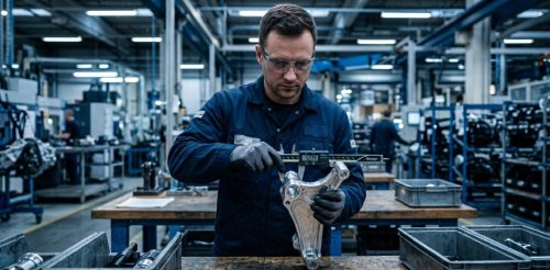
Provide a Delta E color tolerance range when color consistency is critical. Discuss acceptable variation with DEK before production to avoid rejection.
Get started with a stable process and controlled quality. Let's discuss your project.